- Utoljára online
- · Megnézett téma Appsforlife Ticket Wizard 1.1.1
- 2023.05.28.
- 15,540
- 346
- 83
- Díjak
- 6
- 33
File Size: 3.4 GB
Solid Edge is the most comprehensive hybrid 2D/3D CAD system, using synchronous technology to speed up the design and editing process, as well as advanced support for reusing imported geometry. Solid Edge is a key component of the Velocity Series™ portfolio of solutions and features superior tools for part and assembly modeling, drafting, transparent data management, and built-in finite element analysis to help address the growing complexity of product designs. The new version of Solid Edge offers enhanced functionality based
on synchronous technology, which significantly speeds up the product design process, simplifies making changes, importing and applying data created in various CAD systems. The latest version includes improvements in finite element analysis, design data management, and more than a thousand user-defined changes.
By realizing the vision of synchronous technology, Siemens PLM Software has expanded the possibilities of using synchronous technology throughout the system. In addition to the support for modeling parts and sheet bodies implemented in previous versions, synchronous models can be used directly in assemblies - for example, when designing pipelines, trusses, electrical wiring and other types of products. For the first time, associativity between synchronous parts has been introduced, allowing the user to create and edit their design before, during or after the assembly design process.
Solid Edge provides the ability to work with both synchronous and conventional (design tree) structural elements in a single integrated design environment. Users can use synchronous features to speed up the design process and flexibly edit models, and tree-based features to design cast and machined parts. Design tree elements in existing models can be selectively converted to synchronous elements, giving the designer greater flexibility and ease of use of the system.
As more businesses migrate from other 3D systems to Solid Edge and take advantage of synchronous technology, the ability to combine 2D drawings with existing 3D models has become another way to improve productivity. Manufacturing dimensions in 2D drawings can now be automatically transferred to the corresponding imported 3D model. The resulting "production" 3D dimensions can be immediately edited, and the imported 3D model is changed simultaneously due to synchronous technology.
Solid Edge has a finite element analysis application that includes new types of loads - torque and cylindrical support loads, user-defined constraints, as well as new ways to connect parts in assemblies, such as bolted connections and rib connections for sheet metal parts. Model simplification tools allow you to quickly obtain calculation results, and improved visualization tools allow you to see the model from the inside. The model can be adjusted both using synchronous technology and using a construction tree. Solid Edge provides part and assembly model control early in the design process, reducing time to market and reducing prototyping costs.
Solid Edge has thousands of customer-specified enhancements that further enhance the value of the product throughout the product design process. New functionality has been added to various modules, including sheet metal, piping and truss modeling, assembly management, and drafting tools. Improvements to the sheet metal design environment include new types of corner snaps, an etch element for part symbols and other geometry, and technological elements in sheet metal flattening, such as shipping tabs. Solid Edge continues to raise the bar in the area of drawing creation, in which you can now transfer all technological dimensions and designations, designations of parts in an assembly, and even represent parts with different line colors on the drawing, borrowing them from the 3D model. New "international" drawings allow you to use different character sets in different languages of the world in a single drawing or callout. The simplified user interface includes a fully customizable radial menu that reduces mouse movements. Transparent control dialogs for structural elements and parts, as well as reduced size command dialogs, provide the largest area of the graphical workspace
Databases of standard parts of various standards for Solid Edge 2024.
Compatibility: Siemens Solid Edge 2024 with a fix from SSQ.
System requirements: Win 10
Internet Explorer 11.0 and higher
At least 2 GB RAM
True Color (32-bit) or 16 million colors (24-bit)
Screen Resolution: 1280 x 1024 or higher, following the manufacturer's recommendations
Supported languages : Chinese Simplified, Chinese Traditional, Czech, English, French, German, Hungarian, Italian, Japanese, Korean, Polish, Portuguese-Brazilian, Russian, Spanish
and more...
System Requirements: pre-installed Siemens Solid Edge 2024
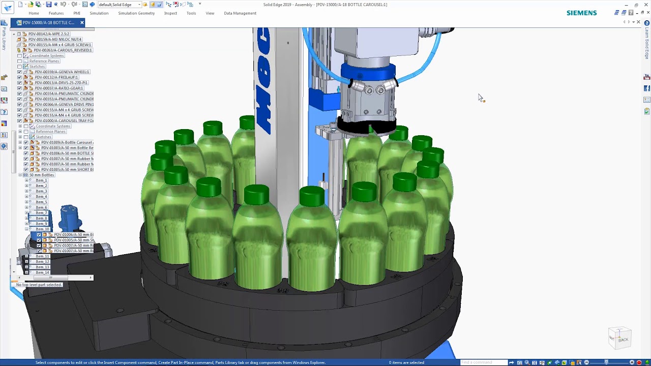
Screen :
What's New
A tartalom megtekintéséhez szükséges:
Bejelentkezés
vagy
Regisztráció
to view spoiler content!
HOMEPAGE
Code:
Linkeket csak regisztrált tagok láthatják! Bejelentkezés ::: Regisztráció
Code:
Linkeket csak regisztrált tagok láthatják! Bejelentkezés ::: Regisztráció